|
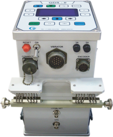
GDS VibSim
Vibrator Simulator
General
The GDS VibSim Vibrator Simulator is designed to test and troubleshoot many vibrator control systems, such as GDS-I, GDS-I PLUS, GDS-II (Specgeofizika), Force I, Force II, Force III (Seismic Source), Vicont Sweep Master (Geoswip), Advance II and Advance III (Pelton).
Any of these systems would «see» a GDS VibSim unit as a seismic vibrator complete with all sensors and controls. Thus, the simulator may be used both to test vibrator control systems and to train vibrator operators without any fear that a trainee error will result in expensive repairs of a damaged vibrator's hydraulics system.
|
The simulator's interface functionality includes:
- simulator's power indicator (+12 V);
- plate position signals (FULL UP, HALF UP, FULL DOWN, HALF DOWN);
- torque motor data;
- servo-valve data;
- valve position;
- reaction mass position;
- baseplate and reaction mass accelerometer power indicator, + 30 V;
- loop reaction mass accelerometer;
- similarity reaction mass accelerometer;
- loop baseplate accelerometer;
- similarity baseplate accelerometer;
- PTT radio mode indicator;
- baseplate ground contact LIFT XD SWITCH;
- radio connector.
The TORQUE MOTOR, VALVE and MASS indicators display, respectively, the toque motor current, valve position and reaction mass position. The TORQUE MOTOR, VALVE and MASS potentiometers enable users to adjust simulated zero levels as needed. Both, the LED indicators and potentiometers, make the simulator suitable for training vibrators' operators.
The front panel has a test connector to output the following signals:
- POWER = power source voltage (activated by a jumper);
- TORQUE MOTOR = torque motor current;
- VALVE LVDT PRIM = valve position circuit, primary;
- VALVE LVDT SEC = valve position circuit, secondary;
- MASS LVDT PRIM = reaction mass position sensor, primary;
- MASS LVDT SEC = reaction mass position sensor, secondary;
- LOOP MASS ACC = loop reaction mass accelerometer;
- SIM MASS ACC = similarity reaction mass accelerometer;
- LOOP BP ACC = loop baseplate accelerometer;
- SIM BP ACC = similarity baseplate accelerometer;
- RADIO SPEAKER = radio output (speaker);
- RADIO MIC = radio input (mike);
- RADIO PTT = radio PPT button.
Operating the Vibrator Simulator
To operate the Simulator, proceed as follows:
- Connect the Vibrator Simulator to a 9-36 V/3 A power supply (variable voltage is ok) using the POWER/RADIO cable.
- Connect the Vibrator Control System to the Vibrator Simulator using the VIBRATOR ELECTRONICS cable.
- Power on the Vibrator Simulator first. Then power on the Vibrator Control System.
- For liner simulation load the following weight values to the Vibrator Control System:
— downward pressure = 14,300 kg;
— reaction mass weight = 1,700 kg;
— baseplate weight = 1,030 kg.
- Move the baseplate down (until the FULL DOWN indicator is on);
- Make sure that the LIFT XD SWITCH is ON (the hydraulic pressure is applied and the baseplate is in contact with the ground and pushed down).
- Initiate the vibrator calibration procedure from the control module.
Once calibration is finished, sweeps may be initiated manually or by launching VP.exe on a computer.
When a sweep is initiated the LEDs display simulated changes in the torque motor current, valve position and reaction mass position.